- 您现在的位置:买卖IC网 > Sheet目录3882 > PIC18F452T-E/ML (Microchip Technology)IC MCU FLASH 16KX16 A/D 44QFN
PIC16C9XX
DS30444E - page 110
1997 Microchip Technology Inc.
LCDSE
923
924
1111 1111
uuuu uuuu
LCDPS
923
924
---- 0000
---- uuuu
LCDCON
923
924
00-0 0000
uu-u uuuu
LCDD00
to
LCDD15
923
924
xxxx xxxx
uuuu uuuu
TRISF
923
924
1111 1111
uuuu uuuu
TRISG
923
924
1111 1111
uuuu uuuu
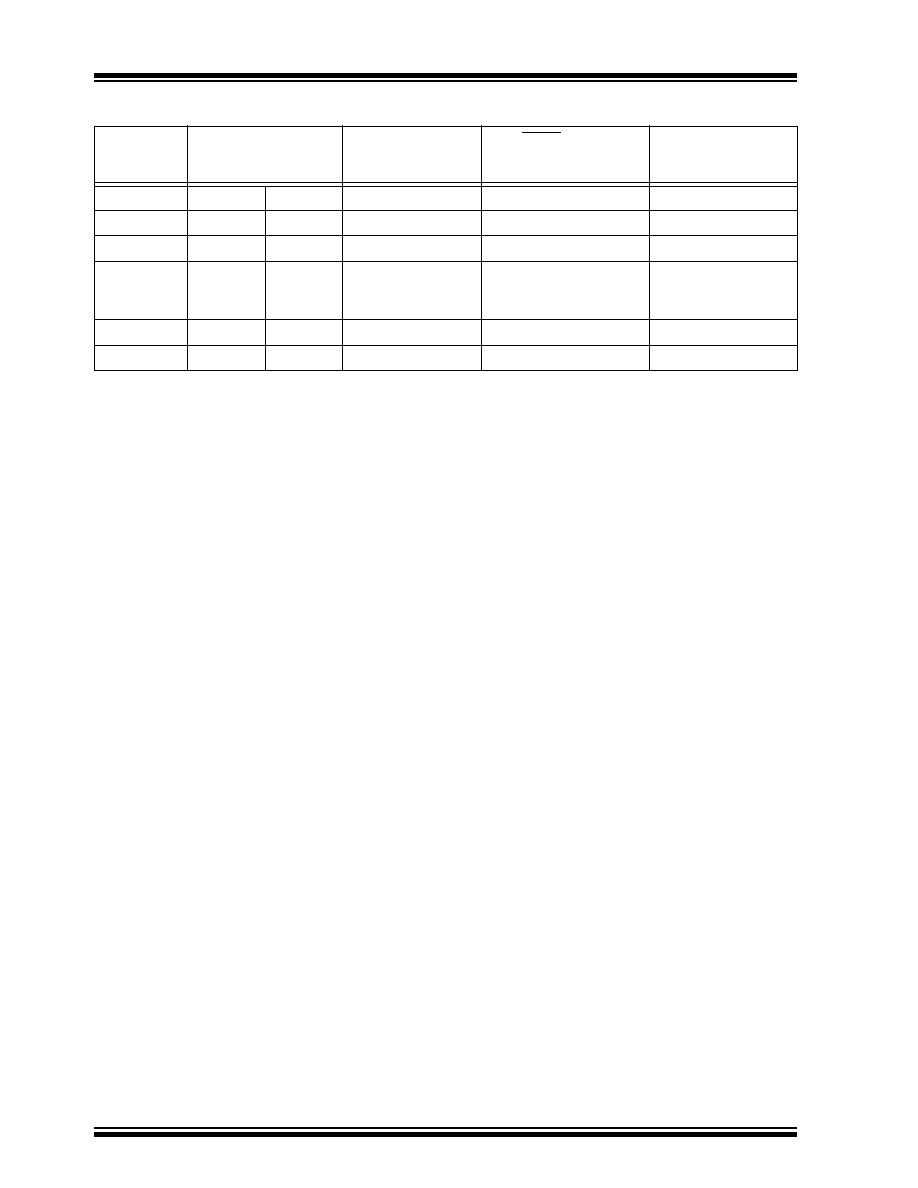
TABLE 14-6: INITIALIZATION CONDITIONS FOR ALL REGISTERS (Cont.’d)
Register
Applicable Devices
Power-on Reset
MCLR Resets
WDT Reset
Wake-up via
WDT or
Interrupt
Legend: u = unchanged,
x
= unknown,
-
= unimplemented bit, read as '0', q = value depends on condition
Note 1: One or more bits in INTCON and/or PIR1 will be affected (to cause wake-up).
2: When the wake-up is due to an interrupt and the GIE bit is set, the PC is loaded with the interrupt vector
(0004h).
3: See Table 14-5 for reset value for specic condition.
4: Bits PIE1<6> and PIR1<6> are reserved on the PIC16C923, always maintain these bits clear.
5: PORTA values when read.
发布紧急采购,3分钟左右您将得到回复。
相关PDF资料
PIC18F442-E/ML
IC MCU FLASH 8KX16 EE A/D 44QFN
PIC18F2539T-I/SO
IC MCU FLASH 12KX16 EE AD 28SOIC
PIC18F4439T-I/PT
IC MCU FLASH 6KX16 EE A/D 44TQFP
PIC16LF77T-I/ML
IC MCU FLASH 8KX14 A/D 44QFN
PIC16F74T-E/ML
IC MCU FLASH 4KX14 A/D 44QFN
PIC16F74-E/ML
IC MCU FLASH 4KX14 A/D 44QFN
PIC18LF2439T-I/SO
IC MCU FLASH 6KX16 EE A/D 28SOIC
PIC18F4539T-I/ML
IC MCU FLASH 12KX16 EE A/D 44QFN
相关代理商/技术参数
PIC18F452T-I/L
功能描述:8位微控制器 -MCU 32KB 1536 RAM 34I/O RoHS:否 制造商:Silicon Labs 核心:8051 处理器系列:C8051F39x 数据总线宽度:8 bit 最大时钟频率:50 MHz 程序存储器大小:16 KB 数据 RAM 大小:1 KB 片上 ADC:Yes 工作电源电压:1.8 V to 3.6 V 工作温度范围:- 40 C to + 105 C 封装 / 箱体:QFN-20 安装风格:SMD/SMT
PIC18F452T-I/ML
功能描述:8位微控制器 -MCU 32KB 1536 RAM 34I/O RoHS:否 制造商:Silicon Labs 核心:8051 处理器系列:C8051F39x 数据总线宽度:8 bit 最大时钟频率:50 MHz 程序存储器大小:16 KB 数据 RAM 大小:1 KB 片上 ADC:Yes 工作电源电压:1.8 V to 3.6 V 工作温度范围:- 40 C to + 105 C 封装 / 箱体:QFN-20 安装风格:SMD/SMT
PIC18F452T-I/PT
功能描述:8位微控制器 -MCU 32KB 1536 RAM 34I/O RoHS:否 制造商:Silicon Labs 核心:8051 处理器系列:C8051F39x 数据总线宽度:8 bit 最大时钟频率:50 MHz 程序存储器大小:16 KB 数据 RAM 大小:1 KB 片上 ADC:Yes 工作电源电压:1.8 V to 3.6 V 工作温度范围:- 40 C to + 105 C 封装 / 箱体:QFN-20 安装风格:SMD/SMT
PIC18F452T-I/PTG
功能描述:8位微控制器 -MCU 32KB 1536 RAM 34I/O RoHS:否 制造商:Silicon Labs 核心:8051 处理器系列:C8051F39x 数据总线宽度:8 bit 最大时钟频率:50 MHz 程序存储器大小:16 KB 数据 RAM 大小:1 KB 片上 ADC:Yes 工作电源电压:1.8 V to 3.6 V 工作温度范围:- 40 C to + 105 C 封装 / 箱体:QFN-20 安装风格:SMD/SMT
PIC18F4539-E/ML
功能描述:8位微控制器 -MCU 24KB 1408 RAM 32 I/O RoHS:否 制造商:Silicon Labs 核心:8051 处理器系列:C8051F39x 数据总线宽度:8 bit 最大时钟频率:50 MHz 程序存储器大小:16 KB 数据 RAM 大小:1 KB 片上 ADC:Yes 工作电源电压:1.8 V to 3.6 V 工作温度范围:- 40 C to + 105 C 封装 / 箱体:QFN-20 安装风格:SMD/SMT
PIC18F4539-E/P
功能描述:8位微控制器 -MCU 24KB 1408 RAM 32 I/O RoHS:否 制造商:Silicon Labs 核心:8051 处理器系列:C8051F39x 数据总线宽度:8 bit 最大时钟频率:50 MHz 程序存储器大小:16 KB 数据 RAM 大小:1 KB 片上 ADC:Yes 工作电源电压:1.8 V to 3.6 V 工作温度范围:- 40 C to + 105 C 封装 / 箱体:QFN-20 安装风格:SMD/SMT
PIC18F4539-E/PT
功能描述:8位微控制器 -MCU 24KB 1408 RAM 32 I/O RoHS:否 制造商:Silicon Labs 核心:8051 处理器系列:C8051F39x 数据总线宽度:8 bit 最大时钟频率:50 MHz 程序存储器大小:16 KB 数据 RAM 大小:1 KB 片上 ADC:Yes 工作电源电压:1.8 V to 3.6 V 工作温度范围:- 40 C to + 105 C 封装 / 箱体:QFN-20 安装风格:SMD/SMT
PIC18F4539-I/ML
功能描述:8位微控制器 -MCU 24KB 1408 RAM 32 I/O RoHS:否 制造商:Silicon Labs 核心:8051 处理器系列:C8051F39x 数据总线宽度:8 bit 最大时钟频率:50 MHz 程序存储器大小:16 KB 数据 RAM 大小:1 KB 片上 ADC:Yes 工作电源电压:1.8 V to 3.6 V 工作温度范围:- 40 C to + 105 C 封装 / 箱体:QFN-20 安装风格:SMD/SMT